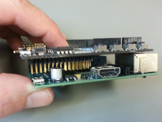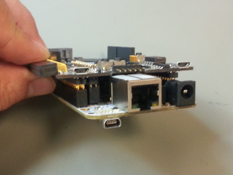
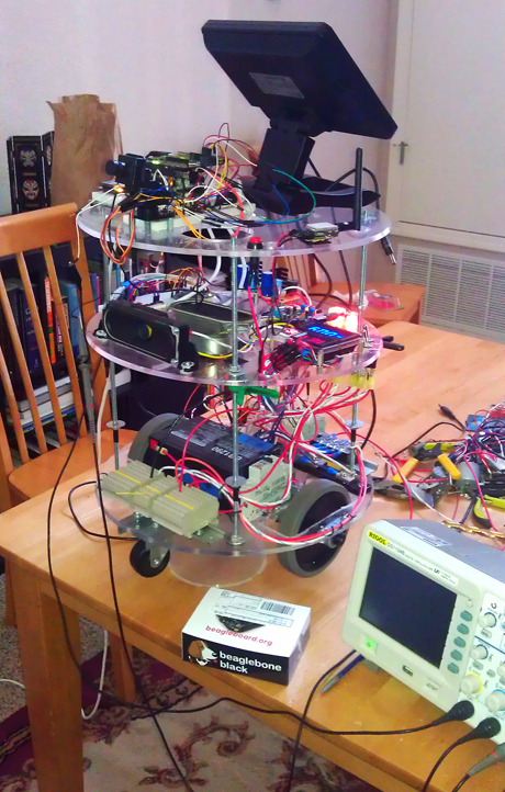
Featuring the ValentF(x) Mark 1 FPGA Board integrated with a BeagleBone Black embedded Linux minicomputer, this open source robot design is a great reference for advanced DIY robotics enthusiasts!
With the novel goal of serving beverages poolside, this hilarious remote controlled robot can interact with customers through wireless video and audio, display information about drink specials, crack jokes using the voice of Stephen Hawking, and drive the contents of its cooler around with a range of 1000 meters!
Coupling the power and flexibility of FPGAs with an embedded Linux software and hardware stack opens up some very interesting possibilities for DIY robotics. The fact that sophisticated electronics and software platforms are now readily available and extremely affordable for the average DIY’er makes this a unique time for hackers everywhere.
All that’s typically needed are some good examples of what’s possible! Here’s a list of some fun electronics / software features the BBot reference design includes:
- It has a Microsoft .NET graphical user interface that uses Windows Presentation Foundation and follows the proliferous Model, View, ViewMode l (MVVM) design pattern.
- There is a real-time, C++ control program that runs on the BeagleBone Black under Angstrom Linux.
- The design has wireless communications of video, audio and control data between the .NET GUI and the embedded control program.
- The Mark 1 board runs an FPGA design that interfaces signals from many of the robot’s hardware devices to the real-time control program.
- On the BBot’s mini display a Qt based graphics program runs and is made possible by the BeagleBone Black’s HDMI video subsystem.
- A camera with a servo driven pan and tilt mount can also be controlled and viewed from the GUI.
- There are various other small systems that can be controlled from the GUI like an alarm buzzer that can be sounded when people try to steal drinks!
The design’s material set will be available for download in mid-September 2013. The ValentF(x) wiki will also be a place for further documentation of the FPGA specific parts of the design.
Stay tuned for more info!
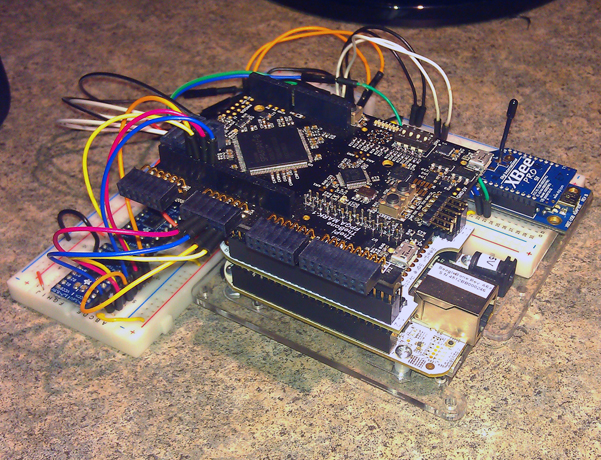
The LOGi boards will be returning to their home roots, Maker Faire New York 2013. Last year we took the alpha version FPGA Mark-1, now LOGi-Mark1, to Maker Faire to see what other FPGA and electronics enthusiasts would think of the design. We got a lot of great feedback and now have some new FPGA flavors including the LOGi-Pi,LOGi-Bone and the LOGi-Mark1. We also have some fun applications that we wish to share that highlight the capability of the FPGA LOGi Family boards.
LOGi FPGA Family
FPGA LOGi Boards at Maker Faire NYC 2013
We will be in Zone C at the Maker Pavilion - see linked map!
Valent F(x) and the LOGi-Team have developed a Family of FPGA development boards based on last years Maker Faire 2013 NYC entry, FPGA-Mark1. We brought FPGA-Mark1 to Maker Faire in order to get feedback in regard to what users were interested in relative to FPGA’s and how they would most like to interface and use an FPGA development board. We took the feedback and have a developed a family of FPGA development boards that implement the feedback that we received last year. We want to bring the family of FPGA development boards back to Maker Faire to show the users and to ask for any feedback or changes that they might be interested in before we release the boards to the market. We have a number of applications that that exemplify the easy to use and highly functional nature that the LOGi boards have to offer.
The LOGi series is a family of FPGA development boards that mitigates the sharp learning curve associated with associated FPGA development and unifies existing hardware interfaces and platforms. FPGA development is an invaluable technology that allows a single board to morph in functionality to fit the needs of changing environments and project and application requirements. The LOGi Family FPGA boards allow beginning or experienced FPGA developers a plug-and-play experience with popular embedded systems including the Raspberry Pi, BeagleBone and the Arduino DUE. The LOGi Team and the LOGi family of boards create a closed loop development solution. The LOGi development boards include applications and hardware for a low-cost, easy-to-use, highly-functional FPGA development solution that complements current COTS hardware peripherals and systems.>
Projects using the LOGi Boards that will be demonstrated:
Bitcoin Mining Rig with the LOGi Boards
The Bitcoin Mining Rig will showcase how the LOGi-Pi or the LOGi-Bone can be used in conjunction with the Raspberry Pi or the Beaglebone to create a fully functional Bitcoin Mining Rig. The LOGi FPGA board handle all of the highly intensive cryptographic number processing involved in the bitcoin authentication process while the Raspberry Pi serves to interconnect the miner to the internet through its ethernet connection.
Machine Vision with the LOGi Boards
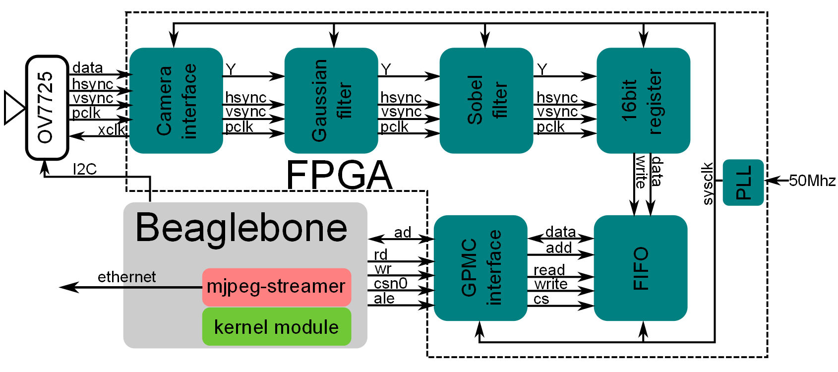
The LOGi boards in conjunction with the Beaglebone or Raspberry Pi create a standalone streaming machine vision platform. This image processing application runs real-time DSP algorithms to create machine vision functionality on the FPGA. Current filters implemented are: 1) unfiltered 2) Guassian Filter 3) Sobel Filter 4) Harris Filter. The processed image is sent to the Pi or the beaglebone, where it is then transported and viewed on an ethernet connected PC using the MJPEG streamer. The image is viewed through a local web browser that displays the streamed video.
Autonomous Vehicle and Robot controller using the LOGi-Pi and the Raspberry Pi
The LOGI-Bot is an autonomous vehicle or general robot controller that utilizes the the general processing of the Raspberry Pi in conjunction with the real-time processing of the LOGi FPGA boards.. Some of the functionality contained within the LOGi-Bot include image processing, PWM, PID control, Encoder counting, WIFI comm, GPS. The LOGi-Bot autonomous vehicle controller (AVC) will be installed on an R/C car and basic autonmous functions will be demonstrated.
Animatronic Telepresence Device
This project, by Jonathan Piat, shows the use of the Rapsberry Pi and the LOGi-Pi as a telepresence device. Instead of building a two way video and audio communication device, this demo relies on the use of an animatronic face to reflect the emotion of the distant user (dynamic emoticon). The audio communication is implemented by a SIP client (linphone) running on a raspberry Pi, while the face animation is handheld by the LOGi-Pi. The LOGi-Pi controls servos (eyebrow and mouth), led matrices (eyes) and RGB leds (hairs) with the onboard FPGA at minimal computing cost for the raspberry pi. This demo will be used as a way for the visitor to interact with a distant LOGi-Pi developer in France.>
Andy Gikling of the LOGi-Team will have his own booth where he will be presenting his own robot based on the LOGi-Mark1 board. Be sure to stop by and check out Andy's great project!
The LOGi-Pi FPGA development board has arrived
The first version of the LOGi-Pi PCBs were received and the first board arcticles have been assembled and are being tested.
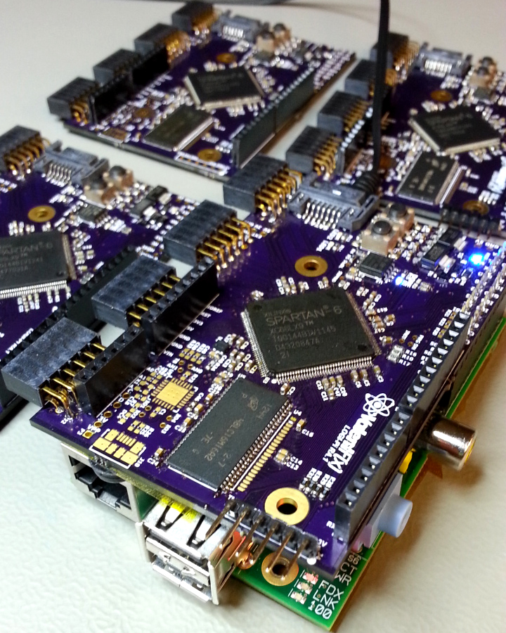
The LOGi-Pi is the latest edition ot the LOGi FPGA family. The LOGi-Pi was designed to add FPGA expansion to the Raspberry Pi in a plug and play manner. The LOGi-Pi is also compatible with direct use the Arduino DUE.
Up to date Schematics and other hardware docs can be found on the LOGi-Boards github repsository.
LOGi Code and project documentation is being hosted on github. Kee up to date with the latest drivers, drivers, project, schematics from the repository. We will also be adding wiki content to include guides and documentation.
Written by Andy Gikling on Thursday, 11 July 2013. Posted in LOGi Guides and Tutorials, LOGi-Mark1
Here is a great Guide to get you up and started quickly on the LOGi-Mark1.
All LOGi boards are capable of having the host, Pi/Bone/Arduino, directly configure the FPGA. This guide contains the required information on how to access the relevant control pin, sequence required to reprogram the FPGA.
LOGi-Mark1 Reconfiguration
The LOGi-Mark1 board contains the LPC1343 MCU. To minimize the number of pins needed from the Host platforms , Bone/Pi, some of the configuration pins are accessed indirectly through the I2C interface. There are basic commands built into the LCP1343 firmware that will setup the required programming sequeces on the configuration pins and status updates can be accessed through the same I2C commands.
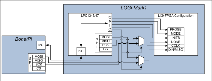
I2C Commands to control the configuration process
//THESE ARE THE CMD VALUES THAT ARE SENT FROM THE MASTER DEVICE 0-256.
- #define I2C_CMD1_PASSIVE_MODE 0X01 //command to go into passive mode
- #define I2C_CMD1_LPC_CFG_MODE 0X02 //command to go have LPC configure
the fpga
- #define I2C_CMD1_DONE 0X03 //did the done bit go high?
- #define I2C_CMD1_LPC_CFG 0X04 //reconfigure the fpga
- #define I2C_CMD1_SLAVE_CFG_INIT 0X05 //reconfigure the fpga
- #define I2C_CMD1_SLAVE_CFG_INIT_STAT 0X06 //reconfigure the fpga
Host command sequece for configuration
1) Power on Pi/Bone/Mark1. The new firmware does not load the bitstream by default if the master(bone pi) is connected.
2) Send CMD 0x05.
- This will toggle the INITB and wait to determine if PROG_B went high. Returns 1 if went high or 0 if did not go high.
- sets the CCLK, datain mux select – selects the Pi/Bone to control the CCLK, DIN FPGA config pins
3) Read CMD 0x06 (optional)
- returns status of configuration sequence, if it worked, you will receive 1 in the second byte read back. byte1 echos the address/ r/w that was sent.
4) begin to clock in the bitstream data
5) CMD 0X03 to read the done status bit. second byte read. (I havn't check the done status bit yet.) If I remember right it may not be working, but for now just look at the done led or otherwise determine if the program is running.
Resources
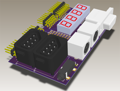
LOGi-MARK-1 EDU Expansion PCB
The Mark-1 educational (EDU) expansion PCB was designed to be used in conjunction with the MARK-1 development platform as an educational tool. The EDU expansion PCB contains peripherals that are compatible with exmaples for the "Pong Chu" book. There were also some extra peripherals added to add bit flavor to the experience. Added peripherals consist of 2 nintendo entertainment system (NES) controllers and an PWM audio output audio jack.
Peripherals on the EDU expansions:
- VGA video output
- PS/2 jacks X2
- Seven Segment Display x 4
- NES video game controller jacks X 2
- Audio Jack 2 channel PWM jack
Resources:
LOGI-MARK1 Sobel Filter Demo
Image Processing
Applications in image processing technology are becoming more and more prevalent with the availability of low cost high performance electronics systems. The addition of image processing algorithms to such systems enables applications such as object tracking and detection, autonomous movement, ambient change recognition, etc. Image processing is known to be very data processing intensive based on the amount of data needed to be processed and the speed which the data needs to be processed. FPGA technology handles both of these requirements very well, which makes FPGA’s, especially in conjunction with high performance embedded systems, a very powerful tool for implementing a vast array of applications.
This is a guide that uses an FPGA in conjunction with a Beaglebone to run a basic image processing application that uses a Sobel filter to process an image. The application is intended to strip any un-needed functionality and allow the user to directly see the image processing algorithms running. The application is designed to be run in “standalone” mode, which eliminates the need for any additional external hardware to be used with the platform. The application takes passes a stock image from the Beaglebone to the FPGA using the GPMC bus. The image is then processed on the FPGA using a Gaussian and Sobel filter. The processed image is then passed back to the Beaglebone where it can then be used for any number of further applications.
Sobel Filter Description
The Sobel operator is used in image processing, particularly within edge detection algorithms. Technically, it is a discrete differentiation operator, computing an approximation of the gradient of the image intensity function. At each point in the image, the result of the Sobel operator is either the corresponding gradient vector or the norm of this vector. The Sobel operator is based on convolving the image with a small, separable, and integer valued filter in horizontal and vertical direction and is therefore relatively inexpensive in terms of computations. On the other hand, the gradient approximation that it produces is relatively crude, in particular for high frequency variations in the image. [1]
Block diagram
Running the Demo Application
1) unzip it and keep the .bit file on the host PC
2) copy all the other files to the beaglebone (scp is your friend)
3) On the beaglebone, go tho the copied directory and enter the following :
chmod 777 make_demo.sh
chmod 777 addr_mux.sh
./make_demo
4) back on the PC side, load the bitsream onto the FPGA, a led should be blinking, then press push button 0 (reset). See the LOGI-MARK1 bitstream loading guide.
5) on the beaglebone side go to the jpeg_grabber folder and enter :
./logibone_demo ./beagle_qvga.jpg
6) this should generate a grabbed_frame.jpg file that you can copy back to the PC (scp again)
Notes
Note that this application was for demo purposes that allow for no additional hardware to be connected to the LOGI boards. The full application would have an external cmos camera connected that is streaming images to the FPGA, which in turn process the images using the Sobel filter. The FPGA then streams the filtered images to the Beaglebone, which can further process them and or send them to an external PC.
See these videos to see a full running application with connected camera:
http://www.youtube.com/watch?v=hSHwD6L7dVQ
http://www.youtube.com/watch?v=DWjhEJdcgR0
Source:
References
[1] http://en.wikipedia.org/wiki/Sobel_filter
[2] Project created by Jonathan Piat
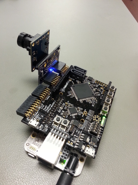
A CMOS camera PCB, "LOGi-Cam", was designed to allow plug and play expansion between LOGi family boards and low cost CMOS cameras. CMOS cameras come with a wide range of available features from low to high resolution to low to high frame rates. The LOGi-Cam makes it easy to add this wide array of camera functionality to the LOGi family of FPGA boards. Additionally the LOGi-Cam PCB allows easy adjustment of required camera system voltages with the flip of a switch.
Additional Features:
- Multiple low cost cameras directly compatible, Flex cable camera or Standard form factor camera compatible
- Regulation voltages can be adjusted by changing the feedback resistors on the variable voltage regulators
- The onboard voltages can be switched between by using the onboard slider switch
- Pin function can be changes using slider switch
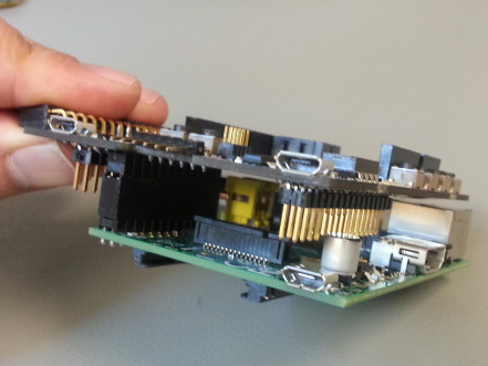
The LOGi-Mark1 can be connected to multiple embedded platforms including the Raspberry Pi, Beaglebone and Arduino. In order for the LOGi-Mark1 to be able to connect to these platforms, headers must be populated that connect to the respective embedded platform. In some cases the end user may wish to be able to connect to multiple platforms in a plug and play manner. It is currently possbile to connect the LOGi-Mark1 to the Raspberry Pi or the Beaglebone by making 2 minor modifications to the LOGi-Mark1.
Modifications:
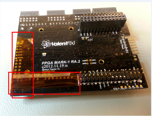
1) Add kapton tape or other similar insulator to the exposed header pins shown on the bottom of the LOGi-Mark1 as shown in the red boxes in the image below.
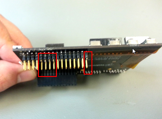
2) Cut the outter row of pins enclosed in the rectangular box below. Note DO NOT CUT THE INNER ROW OF PINS - MAKE SURE YOU HAVE SELECTED THE CORRECT PINS TO CUT BEFORE CUTTING. Counting from left to right as shown in the picture, pins 5,6,7,8 and 16 can be cut. These pins are unused on the beaglebone and need to be cut in order to not conlict when placed with the Raspberry Pi.
Picture of the modified board on the beaglebone and the Raspberry Pi after modification:
