Best Awesome Content
-
Logibone with BeagleBone Black Wireless (booting from eMMC)
Hello all,I'm posting this here in hopes that I can save someone else the time and effort I've spent on trying to get the Logi-Bone R 1.5.1 (same as V2 Logibone on element14) communicating over SPI with the new BBB Wireless which runs a distribution of Debian Jessie. Below are the steps that I took, the biggest discovery for me was finding danielvilas' post here which explains how to use the logi-kernel repo to place the proper device tree overlay in /lib/firmwareDISCLAIMER: I am not an expert with UNIX based systems or FPGA but I have dipped my feet in both before. If you see something that I am doing that is totally wrong and terrible practice (like when I add a root profile just in case I need it later....) please don't hesitate to point it out. I really just made this post to consolidate what I could find about getting BBB Wireless, a version of Jessie, and a Logi-bone playing together nicely while the OS is on eMMC.. Cheers!## Begin by flashing eMMC with (Debian 8.7 2017-03-19 4GB SD LXQT ) then:################################################################## Set up wifi so we can connect without usbsudo connmanctltether wifi disableenable wifiscan wifiservicesagent onconnect wifi_#_## connect to your listed router wifi_#_# by entering appropriate passkey, then exit connmanctl by typing:exit# Adding a root access profile to the boardsudo su# enter debian password (temppwd)passwd# enter and repeat new root password then turn off super user mode with:exit# edit this configuration file to confirm the root profile will be accessible over sshsudo nano /etc/ssh/sshd_configCHANGE LINE FROM:PermitRootLogin without-passwordTO:PermitRootLogin yes# restarting ssh service to reflect updated permissions of root/etc/init.d/ssh restartsudo reboot### Daniel Vilas' additions (from discussion "beaglebone shared pins, dts overlay")# Update Kernelcd /opt/scripts/tools/git pullsudo ./update_kernel.shsudo reboot# Update software and Install DTCsudo apt-get updatesudo apt-get install device-tree-compilersudo reboot# Create and copy Device tree overlay from .dtscd /home/debiancd logi-kernel/beaglebone-black/logibone_r1/dtc -O dtb -o BB-BONE-LOGIBONE-00R1.dtbo -b 0 -@ BB-BONE-LOGIBONE-00R1.dtssudo cp BB-BONE-LOGIBONE-00R1.dtbo /lib/firmware# Add new device tree overlay to initial ram file systemsudo update-initramfs -uk `uname -r`sudo poweroff############################################################ For ESD protection: !!!DISCONNECT ALL WIRES!!! ### Physically install Logibone 1.5.1 at this point, then: ###########################################################cd /home/debiancd logi-tools/unified_loader/nano logi_loader.hchange all /dev/spidevX.X to dev/spidev1.0cd ..sudo ./install_logibone.shsudo rebootcd /home/debiangit clone -b logibone https://github.com/fpga-logi/logi-apps.gitlogi_loader logi-apps/blink_led_app/logibone_r1_blink.bitsudo apt-get autoremovesudo reboot#####################################################################################Now that the Logibone is physically installed we can successfully write .bit files to it, we will look at the modifications needed to allow wishbone bus comm for applications such as streaming bytes of audio from a pdm mic on one of the logibones PMOS ports, or other sensors that have been configured with the FPGABy default, the uEnv.txt file in /boot will have lines commented out that look like this:##Example v4.1.x#cape_disable=bone_capemgr.disable_partno=#cape_enable=bone_capemgr.enable_partno=change these lines to:cape_disable=bone_capemgr.disable_partno=BB-BONELT-HDMI,BB-BONELT-HDMINcape_enable=bone_capemgr.enable_partno=BB-SPIDEV1,BB-SPIDEV0,BB-SPIDEV2The first line will disable to HDMI output relinquishing control of the three SPI pins which are then enabled for SPI functionality with the second lineafter saving the changes to uEnv.txt, reboot and cat the following file:cat /sys/devices/platform/bone_capemngr/slotsyour output should look like this:cat /sys/devices/platform/bone_capemgr/slots0: P----- -1 BB-BONE-LOGIBONE,00R1,VALENTFX,BB-BONE-LOGIBONE1: PF---- -12: PF---- -13: PF---- -14: P-O-L- 0 Override Board Name,00A0,Override Manuf,BB-SPIDEV15: P-O-L- 1 Override Board Name,00A0,Override Manuf,BB-SPIDEV0I know you are probably concerned, as I was, about the lack of Loading being indicated in the slots file, but if you re-runlogi_loader /home/debian/logi-apps/blink_led_app/logibone_r1_blink.bitIt should still be loading .bit files properly.## A caveat I'm realizing about Startup scripts on the BBB WirelessOn the regular BeagleBone Black, if I wanted to add a script (in my example called recorder_startup.sh) to the initialization scripts of the BBB I would create a soft link of the desired script in the init.d folder of /etc and then update the init.d depend.start scripts by doing the following:sudo ln -s /home/debian/jack/recorder/recorder_startup.sh
/etc/init.d # creates soft linksudo update-rc.d recorder_startup.sh defaults # updates init.d scripts to add to depend.start
In my recorder_startup.sh script, a C function called read_mic_data is called and I have found that on the BBB Wireless, for some reason, two instances of the read_mic_data program will be running if I run the startup script using just these steps, however, I can overcome this odd behavior by adding line
sleep 30
to the top of recorder_startup.sh. Has anyone else experienced this increased boot time? I think it is possible that the init scripts are being called twice in the startup of this kernel and perhaps adding the sleep line to the script will cause the first call of the startup script to

-
logi pi schematic jp11
See attached.
-
Help getting going with logi-matrix
I managed to drive a 32x32 RGB Panel with the tips above.
Looking at the vhd files of "logibone_mat.xise" is it possible to drive a 32x64 Panel with minor adjustments?
Setting nb_panels : positive := 4 for two 32x64, does not work nor does nb_panels : positive := 2.Any ideas? Also the python script to display full-screen rectangle:map = ()g = 0x00F0count = 0for c in range(1024):g = count << 4map = map + (g & 0xFF, ((g >> 8) & 0xFF))count = count + 1if count > 15:count = 0logi.logiWrite(MAT_ADDR, map)time.sleep(3)Leaves out a middle column as well as the first and last on a 32x32 Panel. Why is that?I wished I could use Glen Akins`s version but loading the bitfile will yield that my Revision (R1.5) of logibone is incompatible.
How could one account for that in the .xise file? -
Programming the Logi-Pi-2 flash in Standalone Mode?
Okay - worked it out. An MCS file must be created from the bit file, and downloaded to the flash. The main links for reference are:https://www.xilinx.com/support/documentation/sw_manuals/xilinx11/pim_p_creating_prom_file_spi_single.htmAnd here's an example using the Blink project for anyone else who's interested.1. In Impact, open up the 'PROM File Formatter' and configure as below (choose the output file name and location as you desire). Click OK.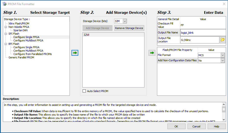 2. Add the BIT file when prompted and Generate the PROM file (aka an MCS file).
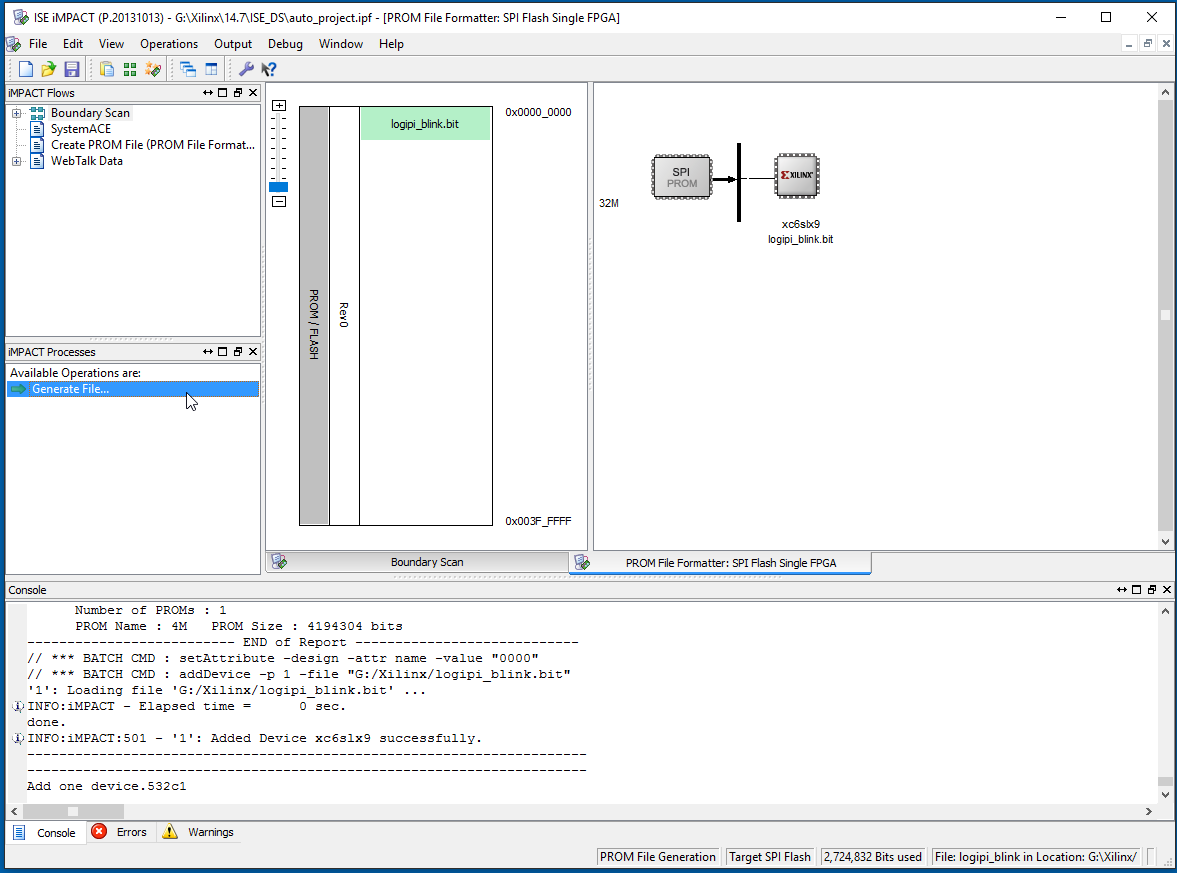 3. Back in Impact, create a project with the Spartan 6 FPGA, and right-click to 'Add SPI/SPI Flash...'
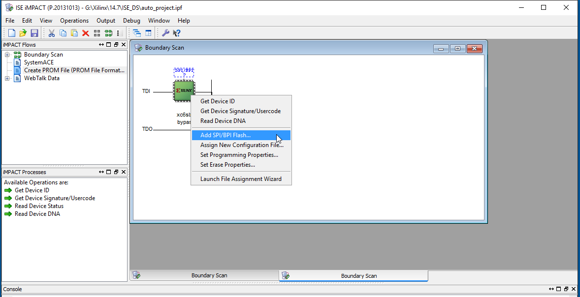 4. Add the MCS file created in step 2 and click Open.
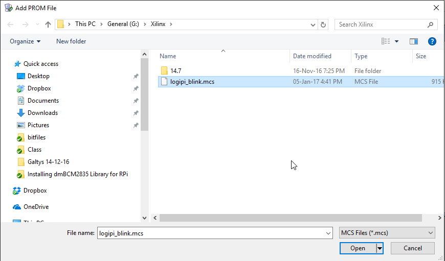 5. Select the correct SPI device in the drop-down list (S25FL032P) and click OK
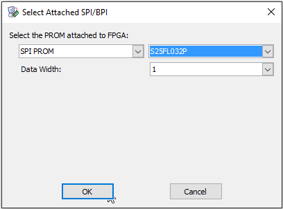 6. Click on the green FLASH icon and select Program.
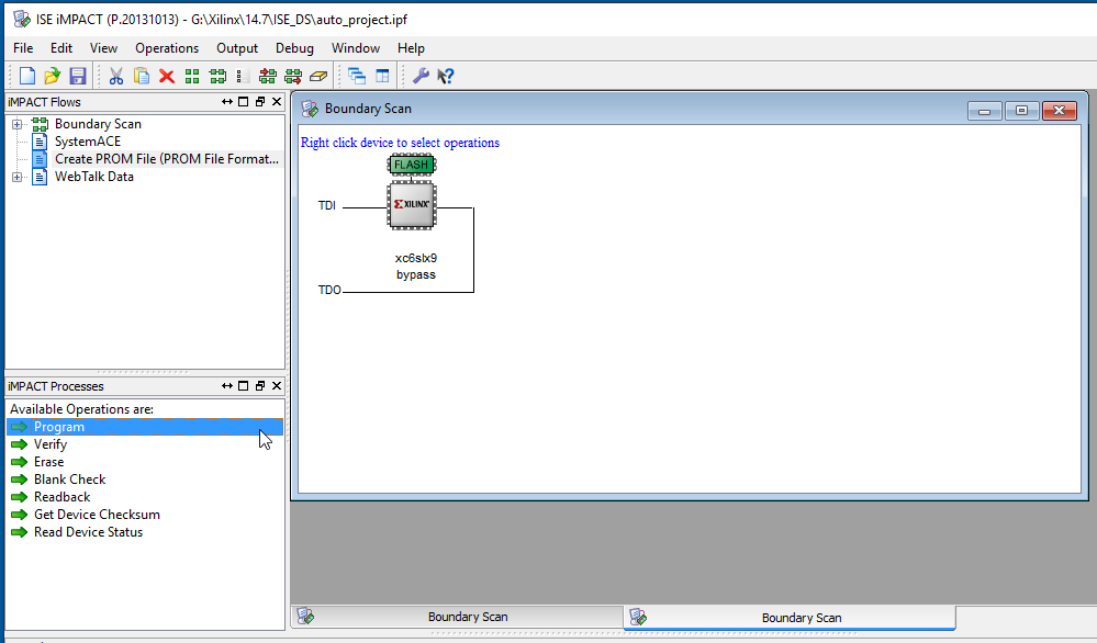 7. Choose options as below and click OK:
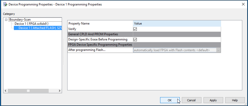 8. The flash is programmed (this can take a while)...
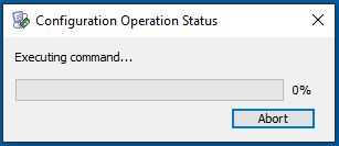 9. The Program Succeeded message should appear, and the code should be running (in my simple example, the LEDs are flashing). When the board is powered off and on, the FPGA will also be configured from the flash as desired.
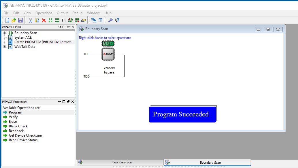
-
SDRAM Controller for LogiBone 1.5.1
Jones,The SDRAM driver worked just as good for the LogiBone 1.5.1.Thanks for your input.-Kumar
-
Problem with running blink test. 'Init pin not going high!'
here is a quick video showing both LOGi Pi and BrickPi working at the same time, thanks for the tips and help.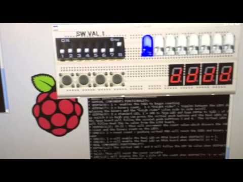
-
Configuring Logi-Bone using Non-OS environment
Let me know if you encounter any problem with this, i'd be happy to help debugging the code.

-
Problem booting Beaglebone Black with LogiBone installed
Great ! You messages you see are the one from the new loader and you can see that your board was identified as a LOGIBONE_R1.5.
Don't hesitate to ask on this forum if you encounter any problem, we will be happy to help.

-
Hidden device tree location
Hi,
to get auto loading of the device-tree overlay for a given beaglebone cape, the device-tree must reside in the kernel itself and not in lib/firmware. This is why the device-tree configuration does not appear in lib/firmware. To change the deveice-tree configuration, you must re-compile the kernel with your patch deice-tree configuration and then just update the kernel file (uImage) on your distribution filesystem.
A way is to disable auto-loading of the cape by wiping clear the identification eeprom of the cape and then load you own device-tree configuration (dtb) manually. To do this you can take the init_eeprom script from logi-tools (https://github.com/fpga-logi/logi-tools/blob/master/init_logibone/init_eeprom.sh) and replace :
cat data.eeprom > /sys/bus/i2c/drivers/at24/1-0054/eeprom
with
dd if=/dev/zero of=/sys/bus/i2c/drivers/at24/1-0054/eeprom bs=1 count=256
This should zero the eeprom and allow you to load your device tree overlay manually. When you have a working overlay i advise to recompile the kernel with it and restore the eeprom content.
Regards,
Jonathan Piat

-
LOGI-PI-2
Hi @tmbartonIt sounds like there has been a lot of confusion - sorry about that. I have notified them that the current MSRP's are listed in error and they are working on getting it fixed.I think that the email about no more LOGI boards shipping must have been in regard to teh version "1" which is not technically FCC/CE compliant.Let me know if you plan on spinning your own board and I can ensure that it works out the first time.I do have leftover R1.0 stock that I can ship with a nice discount, if you would like to get a board sooner than later. You can email support at valentfx dot com.I will work on a getting a wiki page up that descrbies the differences from R1->R1.5 (going to be confusing with E14 calling it "2").* added gpio expander to allow i2c to control the fpga configuration pins rather than using Rpi GPIO* Added uUSB connector to allow additional power to be supplied to the LPi in the case of high powered applications* Moved the main Comm SPI pins off the of the fpga config/flash pins so that the FPGA can access and use flash while communicating with the Rpi.* FCC/CE certifiedCheers.


