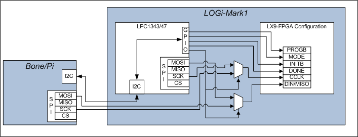
All LOGi boards are capable of having the host, Pi/Bone/Arduino, directly configure the FPGA. This guide contains the required information on how to access the relevant control pin, sequence required to reprogram the FPGA.
LOGi-Mark1 Reconfiguration
The LOGi-Mark1 board contains the LPC1343 MCU. To minimize the number of pins needed from the Host platforms , Bone/Pi, some of the configuration pins are accessed indirectly through the I2C interface. There are basic commands built into the LCP1343 firmware that will setup the required programming sequeces on the configuration pins and status updates can be accessed through the same I2C commands.

I2C Commands to control the configuration process
//THESE ARE THE CMD VALUES THAT ARE SENT FROM THE MASTER DEVICE 0-256.
- #define I2C_CMD1_PASSIVE_MODE 0X01 //command to go into passive mode
- #define I2C_CMD1_LPC_CFG_MODE 0X02 //command to go have LPC configure
the fpga
- #define I2C_CMD1_DONE 0X03 //did the done bit go high?
- #define I2C_CMD1_LPC_CFG 0X04 //reconfigure the fpga
- #define I2C_CMD1_SLAVE_CFG_INIT 0X05 //reconfigure the fpga
- #define I2C_CMD1_SLAVE_CFG_INIT_STAT 0X06 //reconfigure the fpga
Host command sequece for configuration
1) Power on Pi/Bone/Mark1. The new firmware does not load the bitstream by default if the master(bone pi) is connected.
2) Send CMD 0x05.
- This will toggle the INITB and wait to determine if PROG_B went high. Returns 1 if went high or 0 if did not go high.
- sets the CCLK, datain mux select – selects the Pi/Bone to control the CCLK, DIN FPGA config pins
3) Read CMD 0x06 (optional)
- returns status of configuration sequence, if it worked, you will receive 1 in the second byte read back. byte1 echos the address/ r/w that was sent.
4) begin to clock in the bitstream data
5) CMD 0X03 to read the done status bit. second byte read. (I havn't check the done status bit yet.) If I remember right it may not be working, but for now just look at the done led or otherwise determine if the program is running.
Resources