Programming the Logi-Pi-2 flash in Standalone Mode?

Hi, I've had a look through various posts but can't find what I'm looking for. Basically I want to use the Logi-Pi-2 board in standalone mode, and so I want to program the configuration flash (U10) on the board so that it will auto-configure the FPGA on power-up. I'm using the JTAG interface (J5) and a Xilinx JTAG-USB cable and using Impact I can see the Spartan 6 in the JTAG chain, but not the flash (see attached). Can the Flash be programmed using the JTAG port, and if so, how? And if not, how do I program the flash in stand-alone mode?


image
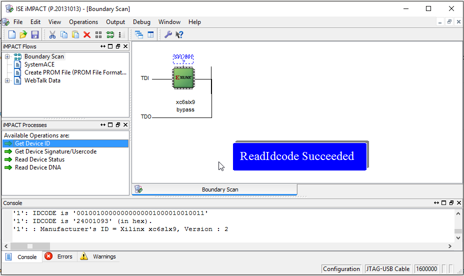
Logi-Pi-2 Standalone JTAG.png
928 x 552 - 41K

Comments

  • Okay - worked it out. An MCS file must be created from the bit file, and downloaded to the flash. The main links for reference are:

    https://www.xilinx.com/support/documentation/sw_manuals/xilinx11/pim_p_creating_prom_file_spi_single.htm


    And here's an example using the Blink project for anyone else who's interested.

    1. In Impact, open up the 'PROM File Formatter' and configure as below (choose the output file name and location as you desire). Click OK.

    image


    2. Add the BIT file when prompted and Generate the PROM file (aka an MCS file).
    image

    3. Back in Impact, create a project with the Spartan 6 FPGA, and right-click to 'Add SPI/SPI Flash...'

    image

    4. Add the MCS file created in step 2 and click Open.


    image


    5. Select the correct SPI device in the drop-down list (S25FL032P) and click OK

    image

    6. Click on the green FLASH icon and select Program.

    image

    7. Choose options as below and click OK:

    image


    8. The flash is programmed (this can take a while)...

    image

    9. The Program Succeeded message should appear, and the code should be running (in my simple example, the LEDs are flashing). When the board is powered off and on, the FPGA will also be configured from the flash as desired.

    image
    1.png 37.6K
    2.png 55.6K
    3.png 44.2K
    4.png 29.1K
    6.png 39.8K
    7.png 17.9K
    8.png 3.6K
    9.png 40.9K
    1.png
    941 x 549 - 38K
    2.png
    1177 x 873 - 56K
    3.png
    1178 x 604 - 44K
    4.png
    870 x 511 - 29K
    5.png
    408 x 302 - 6K
    6.png
    999 x 586 - 40K
    7.png
    948 x 406 - 18K
    8.png
    307 x 133 - 4K
    9.png
    1034 x 583 - 41K
    hexreader
  • edited January 2017
    I was working on instructions, but you beat me to it.  Very nice and thanks for sharing!

    Something to note is that is the Mode pins and their state.  The gpio expander can conflict if not careful.  The loader by default leaves the mode pins in the slave config state, but if modified could configure otherwise.  Also the solder jumper can force a wrong pin state.  Also there is a MUX to effectively disconnect the Pi/Bone MOSI/SCK pins from the flash/config pins so that flash can be used by the FPGA with no conflict from these pins. 

     
  • attached images
    config2.jpg
    1161 x 349 - 85K
    config.jpg
    629 x 310 - 27K
  • Thanks for the warning. Even though I won't be using an RPi, I still intend to use the I2C SCL/SDA lines from the RPi header to access a custom I2C block on my verilog design. But I might instead use one of the PMOD headers. I think I have enough options that I can avoid any problems.
Sign In or Register to comment.