Howdy, Stranger!
It looks like you're new here. If you want to get involved, click one of these buttons!
LOGI-camera-demo: Pixel Timing

Hey,
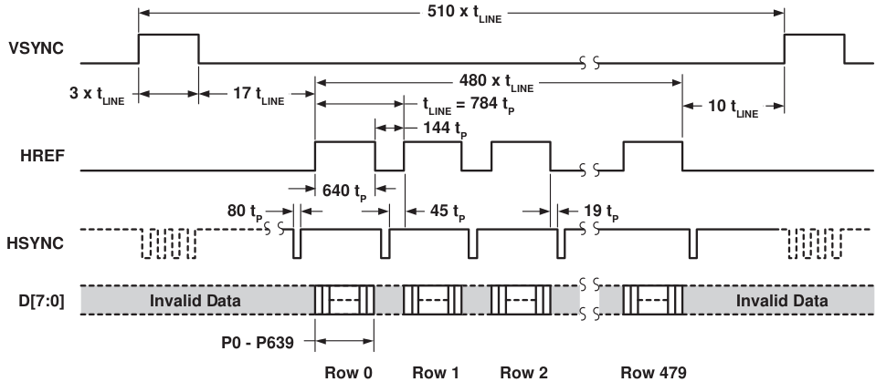
I'm playing around with some image processing and use the Logi-camera-demo as a basis. I can't really figure out the timing protocol of the pixels and the syncs (it is hsync and not href that is outputted, right? the output signal name is a bit confusing) after the yuv_camera_interface module. I got the same timing issue after the down_scaler module. Can someone provide me a timing chart of the pixels, vsync, hsync and href based on the pixel clock after these two modules?
Something similar to this one:
Thanks!
/Amanda
Comments
It's just that I did a simple implementation where I count the edges of the pixel clock between the syncs and it doesn't seem to follow the protocol from the camera. So I guess it has been slightly changed in the modules?
For some details on how the camera is interfaced, read : http://www.element14.com/community/groups/fpga-group/blog/2014/12/17/gradient-filter-implementation-on-an-fpga--part-1-interfacing-an-fpga-with-a-camera
If I want to generate my own pixels (and ignore the camera input) should I have a delay of 17 t_line-19 t_p (where t_p is one cycle and not 2) between vsync falling and hsync rising just like for VGA, or is this delay different for QVGA?
process(pxclk) begin
if pxclk'event and pxclk = '1' then
if hsync = '1' and hsync_old = '0' then
px_count <= 1;
elsif hsync = '0' and hsync_old = '1' then
if px_count > 638 and px_count < 642 then -- should be 2*(320+45+19) = 2*384 = 768
LED(0) <= '1';
end if;
However I had a look at the testbench for the down_scaler and the virtual camera. It seems like the v-cam waits 25-3=22 t_lines instead of 17 t_lines (as told by the camera datasheet) between the end of vsync and the start of the first hsync. Why?